Book Appointment Now

CNC Machined Aluminum Brackets: Design, Finishing and RFQ Guide
CNC machined aluminum brackets combine mounting features, pockets and connection interfaces in a custom component. Learn how to define materials, functional tolerances, finishing and inspection requirements for aluminum mounting brackets, from prototype review to repeat production.
A practical guide to mounting geometry, lightweight design, finishing and inspection for custom aluminum brackets.
CNC machined aluminum brackets support and position components in electronics, automation, robotics and industrial assemblies. Their value comes from the relationship between mounting faces, locating holes and connection features. A bracket can look straightforward while still requiring careful planning to fit correctly after machining and finishing.
For engineering and purchasing teams, the starting point is a clear specification. Identify what the bracket supports, how it is located and which dimensions affect assembly. This guide explains how to turn those requirements into a useful drawing package for custom aluminum machining.
When Does a Machined Aluminum Bracket Make Sense?
A machined bracket is worth evaluating when a design needs integrated mounting faces, pockets, threaded features or a geometry that must match surrounding components. Examples include sensor supports, electronics mounting brackets, robotic accessory mounts and equipment positioning brackets. The appropriate manufacturing route depends on geometry, material, quantity and function.
Compare the proposed route against the actual requirements. A simple shape and a complex pocketed bracket can have very different workholding and inspection needs. Ask the supplier to state what is included in the quotation, including finishing, deburring, documentation and packaging.
Choose the Aluminum Grade and Condition Together
Specify the exact aluminum alloy and condition on the drawing or purchasing specification. The choice should follow loading, stiffness, operating environment, finish requirements and the intended assembly method. A material description that says only aluminum leaves important decisions unresolved.
If your design calls for 6061, include the required condition and material documentation. Review any proposed alternative before production rather than allowing an informal substitution. Our aluminum 6061 CNC machining guide provides related background for discussing a drawing-based project.
Define Mounting Faces, Hole Patterns and Datums
A bracket usually connects two or more parts. Its mounting-hole pattern must therefore be related to the surfaces that locate it in the assembly. Independent checks of hole diameter and overall dimensions may not fully describe whether the bracket will fit.
Mark the primary locating face and identify the secondary references needed to control orientation. Specify the position of locating holes, the relationship between mating faces and any clearance needed around fasteners or adjacent components. Apply tighter requirements to the features that need them, rather than treating every surface as equally critical.
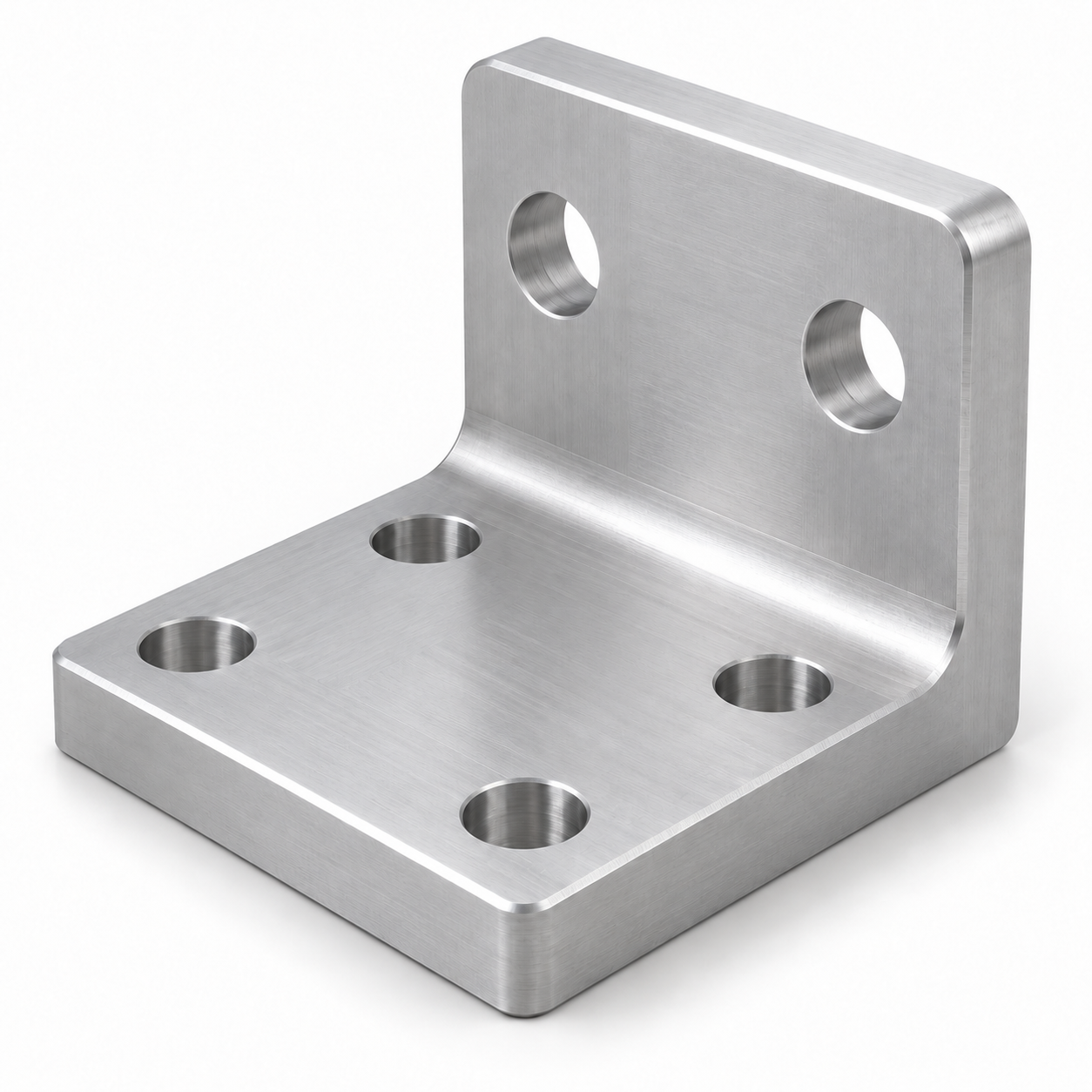
For an angle bracket, consider which surface establishes the assembled position and how the perpendicular mounting face is checked from that reference. For a slotted mounting design, distinguish the adjustment range from the features that must remain accurately located. Resolve disagreements between the model and drawing before releasing the order.
Review Pockets, Internal Corners and Thin Sections
Weight-reduction pockets can change both stiffness and machining access. Review pocket depth, internal corner radii and the support available around thin sections. A feature that is easy to model may require a more involved cutting and workholding strategy.
The manufacturing review should consider whether a cutting tool can reach the feature and whether the component can be held securely. Thin sections also need attention during clamping and measurement. Do not select a wall thickness or corner radius from a generic rule alone; assess it against the actual geometry and function.
Where a design change could improve access, the supplier should explain the proposal and obtain approval. Sandvik Coromant’s milling selection guidance similarly starts with component material, geometry, quality requirements and batch size before selecting a machining strategy.
Plan the CNC Milling Route Around Functional Features
Aluminum CNC milling can produce mounting faces, pockets, slots and hole patterns. Process planning should explain how the part is located between operations and how important feature relationships are maintained.
Features on multiple faces may require additional setups or a multi-axis approach. The decision should follow access and datum requirements. For angled or complex geometry, a review of 5-axis aluminum machining may help establish whether fewer repositioning operations are useful for that component.
Specify Anodizing and Final Acceptance Conditions
If anodizing or another treatment is required, include it in the original RFQ. Identify the surfaces to be treated, masking areas, appearance expectations and any interfaces that require special attention. Confirm whether dimensional acceptance applies before or after treatment.
A coating can affect a mating interface, so discuss the final assembly condition when defining the inspection plan. Color and cosmetic criteria should also be agreed where visible surfaces matter. Specify handling and packaging protection for surfaces that could be damaged during transport.
Inspect the Features That Control Assembly
Inspection should connect drawing requirements to suitable measurement methods. Depending on geometry, checks may include hole size and position, mounting-face alignment, slot dimensions, threaded interfaces and surface condition. For more detail, see our aluminum precision machining and inspection guide.
Agree on the required report format and documentation before ordering. If a bracket has a flexible section, define appropriate support conditions for measurement. A first-article review can provide a structured opportunity to compare the component against the drawing before approving the next production stage.
Illustrative Machining Scenario
Consider a hypothetical aluminum bracket that positions a sensor beside an automated assembly station. The design combines a mounting base, an upright connection face and a pocket intended to reduce mass. The main challenge would be controlling the sensor-hole pattern relative to the base while supporting the upright section during machining.
A proposed route could establish the base as a primary reference, use supported workholding for the upright section and finish the related holes from a consistent locating strategy. Finishing review would identify any surfaces requiring masking. Inspection could then evaluate the hole-pattern position and mounting-face relationship against the agreed datums. The findings would support the customer’s fit evaluation. This is an illustrative planning scenario, not a reported customer project.
Prepare an RFQ for Custom Aluminum Brackets
Provide a current 3D model and dimensioned drawing with matching revisions. Include aluminum grade and condition, quantities, critical dimensions, datum references, threads, edge requirements and finishing instructions. Add the inspection records, material documentation and packaging requirements needed for your project.
Explain the intended function where it helps clarify the drawing. Relevant assembly information can show which faces locate the bracket and where clearance is required. Ask the supplier to record any assumptions in the quotation so competing offers can be compared against the same scope.
Frequently Asked Questions
Should every bracket dimension have a tight tolerance?
Tolerances should follow function. Identify the interfaces that control fit and alignment, then review achievable requirements for the specific material, geometry and finish.
Can the same design support prototypes and repeat orders?
Yes, provided the approved revision and acceptance requirements remain applicable. Review the manufacturing and inspection plan when the quantity or design changes.
What should be confirmed before anodizing?
Confirm treatment specifications, masking, appearance criteria and the stage at which final dimensions are accepted. Resolve these details before the machining route is finalized.
Request a Drawing Review
For CNC machined aluminum brackets, a complete specification provides a stronger basis for evaluating the machining route, finish and inspection scope. Send your drawings for an aluminum machining quotation, together with material requirements, quantities and the features most important to your assembly.
Technical reference: Sandvik Coromant milling selection guidance.